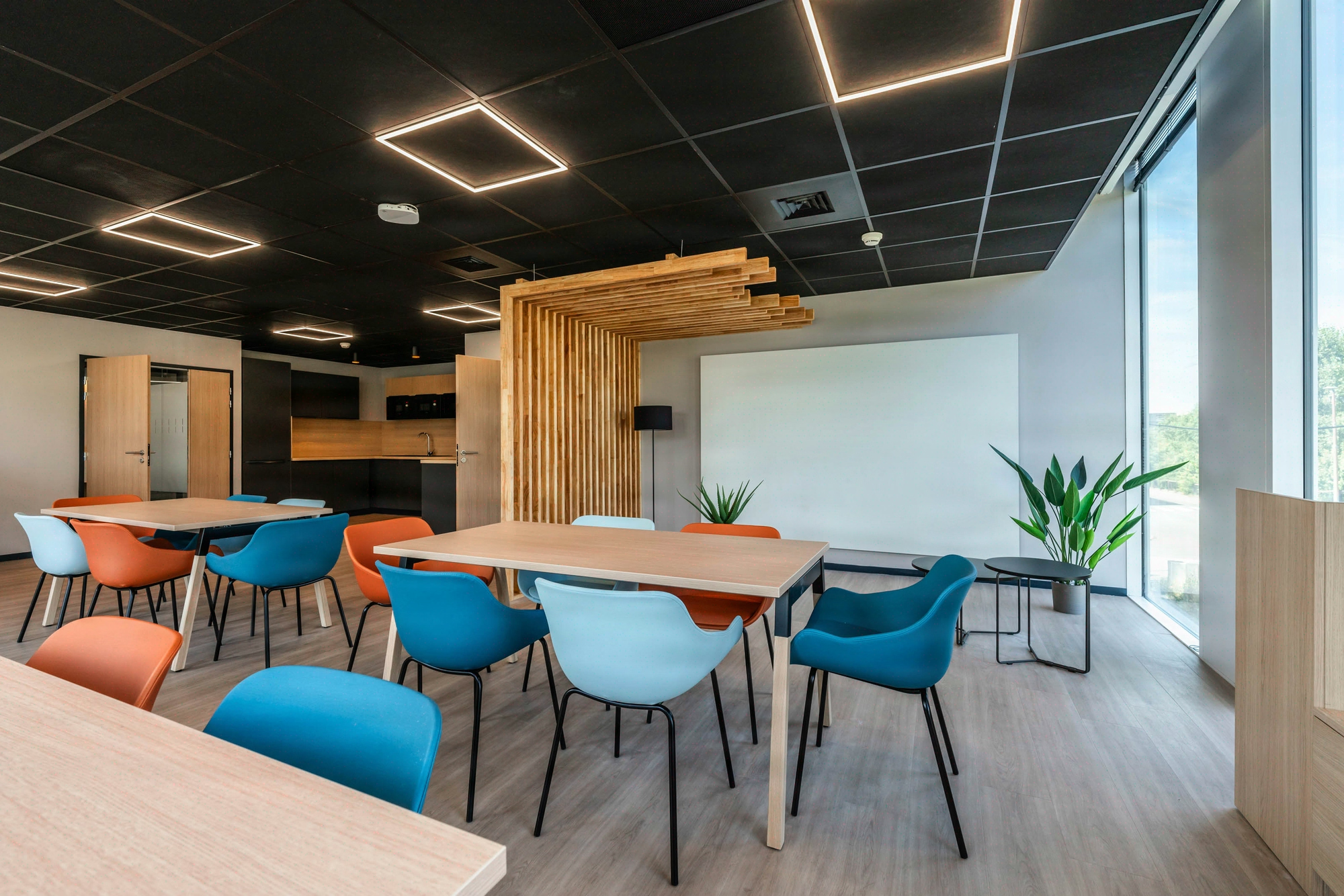
Backlit LED Partitions: Balancing Aesthetics and Technical Constraints
Three structuring tensions to settle from the design stage
A backlit LED partition without a driver access hatch is doomed to partial removal between 18 and 30 months after handover: NF C 15-100 and NF EN 12464-1 govern the electrotechnical and photometric aspects, but neither addresses maintenance accessibility, which remains an architect’s decision. LED backlighting turns a glass partition into an architectural statement, but it transfers onto the structure constraints usually borne by light fixtures: heat dissipation, component accessibility, photometric calibration. On backlit office projects, operational feedback identifies two recurring points of weakness, the electronic power supplies and lighting inconsistencies, which account for the bulk of post-handover interventions. Three trade-offs shape the structure: lighting uniformity with an LED/diffuser distance of 8 to 12 cm, maintenance accessibility driven by the driver and not by the LED, and a 10-year TCO incorporating 2 to 3 driver replacement cycles.

LED integration for backlighting generates three tensions that the design must resolve early, before any final costing.
- Lighting performance versus thickness: achieving uniform diffusion requires an LED/diffuser distance of 8 to 12 cm depending on the power and opacity of the satin glass. This distance sets the total partition thickness, generally 14 to 18 cm, and directly impacts the partitioning grid.
- Aesthetics versus maintenance: LEDs have a lifespan of 30,000 to 50,000 h, but drivers fail at 15,000-20,000 h. Without an access hatch, replacement requires partial removal of the partition; with a hatch, the panel’s aesthetics are segmented by the cut lines.
- CAPEX versus OPEX: the initial additional cost of a backlit LED partition remains significant compared to a standard glass partition, while electricity consumption can be reduced by a factor of 4 against equivalent additional overhead lighting.
Our reading differs from the profession’s conventional wisdom on one specific point: the visible driver access hatch is not an aesthetic compromise but a deliberate architectural choice. On the structures we have delivered, those that integrate the hatch lines into the glass layout grid (recessed joint at 600 or 1,200 mm) achieve a more rigorous reading than monolithic structures whose first after-sales intervention creates an unplanned scar. The trade-off is measured in 10-year TCO, incorporating 2 to 3 driver replacement cycles and the operating savings captured over time.
Comparative lifespan of LEDs, drivers and maintenance consequences
The actual lifespan of a backlit partition is never that of the LED alone: it is that of the component that fails first. The table below summarizes the observed differences and their consequences for the maintenance strategy.
| Component | Lifespan | Failure mode | Associated strategy |
|---|---|---|---|
| LED (modules) | 30,000 to 50,000 h | Progressive color drift | Scheduled replacement at end of cycle |
| Driver / power supply | 15,000 to 20,000 h | Outright failure, shutdown | Mandatory access hatch |
| Aluminum profile | > 20 years | Thermal expansion if joints absent | Joint every 3 m |
| Diffuser (satin glass) | > 20 years | Soiling, micro-scratches | Annual cleaning |
LED and driver values from Kytom partner manufacturers’ technical datasheets, cross-checked with internal operational feedback. The operational consequence is clear: the driver dictates the maintenance schedule, not the LED. Any design that makes the drivers inaccessible dooms the structure to heavy removal at the first failure.

Four recurring mistakes at the detailed design stage
Four mistakes recur on projects not controlled upstream, with a direct impact on post-delivery reliability.
- Drivers sized to the bare minimum: without a 20% safety margin, premature overheating causes a series of failures in the first months.
- Thermal expansion of aluminum profiles overlooked: without joints every 3 m, the profiles deform, creating irregular bright spots visible at grazing angle.
- Photometric study omitted: without prior simulation, shadow or overexposure zones appear at commissioning, requiring costly rework.
- No electrical audit of the existing panel: the power added by a backlit partition can trigger unbudgeted upgrades.
The associated best practices come down to four checks carried out at the detailed design stage: a precise photometric specification targeting 300 to 500 lux depending on use (differentiated targets for offices and circulation areas), 20% driver oversizing, expansion joints every 3 m, and a prior electrical audit of the panel and protective devices. These checks eliminate the bulk of the on-site contingencies observed on this type of structure.

For the architect and the project owner: integrating the LED partition into cross-trade coordination
For an architect or a property investor, the backlit LED partition is not a catalog product but a hybrid structure at the interface of four trades: partitioning, electricity, suspended ceiling, and access control when the partition borders an airlock. The professional reading differs from that of the manufacturer.
The architectural challenge plays out on three levels. Layout: the grid of driver access hatches must align with the grid of the satin glass, otherwise the structure presents two competing grids readable at grazing angle. Overall photometry: the backlit partition modifies the illumination of the adjacent floor plate, with a notable added power on the zone, which requires reducing the overhead lighting to meet the renovation target of 2.8 W/m²/100lux of average illumination to be maintained (Filière 3e). Electrotechnical compliance: the structure falls under NF C 15-100, which transfers onto the architect a coordination responsibility that the tender documents must explicitly assign.
The contractual translation is simple: a technical specification that separates the partition trade from the electrical trade without an interface clause systematically produces a handover dispute. On structures delivered by Kytom under design and build, this dispute is neutralized by the single contract. On structures with separate trades, the architect benefits from requiring a photometric commissioning report signed jointly by the two trades.

Kytom’s four-step execution methodology
The execution sequence is based on four steps aligned with the applicable electrotechnical and photometric standards. Step 1, photometric study: Dialux or equivalent simulation, validation of the 300 to 500 lux targets, calibration of the LED/diffuser distance between 8 and 12 cm. Step 2, 1 m² prototyping: leveraging Kytom prototypes, architect cross-validation before series launch. Step 3, coordinated execution: electricity/partitioning interface managed by a single coordinator, in line with our design and build approach mobilizing 4 integrated trades. Step 4, commissioning and photometric report: contradictory on-site measurements, traceability of targets achieved, handover of the maintenance file with the location of driver access hatches.


